- Home
- /
- APXVB4L20B_43-C-I20
APXVB4L20B_43-C-I20
10-Ports, X-Pol, Panel Antenna, 2.0m, 1x698-960/4x1710-2690, 65deg, Integrated RET
Rev : H | Rev date : 13 Mar 2023

This antenna is an ideal choice for Penta band site upgrades for high traffic areas.
It can be used for multiple bands such as LTE 700, Digital Dividend, CDMA, GSM, DCS, PCS, AWS, UMTS and LTE 2600.
FEATURES / BENEFITS
-
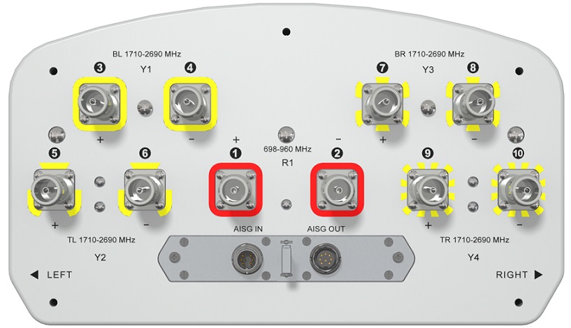
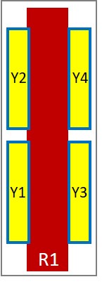
Penta band cross-polarized (10 ports), 1x698-960 / 4x 1710-2690 into a compact size
-
Ultra-broadband design from LTE 700 to LTE 2600
-
High reliability - designed to last in a tower top environment
-
SRET -Field replaceable / ACU HW Version -2.02
-
Compliant with AISG V2.0 and 3GPP
Electrical Specifications |
|---|
| Electrical Specification Header | | Low Band Array (698-960 MHz) [R1] |
| Frequency Band |
MHz |
698-806 |
790-896 |
870-960 |
| Gain Typical |
dBi |
15.2 |
15.9 |
16.3 |
| Gain Over all Tilts |
dBi |
14.9 +/- 0.3 |
15.4 +/- 0.5 |
15.9 +/- 0.4 |
| Azimuth Beamwidth 3dB |
Deg |
65.2 +/- 1.7 |
62.9 +/- 3 |
59.6 +/- 1.7 |
| Elevation Beamwidth 3dB |
Deg |
11.8 +/- 1.1 |
10.5 +/- 0.9 |
9.4 +/- 0.8 |
| Cross Polar Discrimination at Boresight |
dB |
23.9 |
23.2 |
22.5 |
| Cross Polar Discrimination over Sector |
dB |
10.7 |
8.8 |
9.3 |
| F/B at +/-30deg Total Power |
dB |
23.3 |
24.4 |
24.1 |
| First Upper Side Lobe Suppression |
dB |
17.6 |
16.1 |
12.8 |
| Electrical Downtilt |
Deg |
2 to 12 |
| Cross Polar Isolation |
dB |
26 |
| Interband Isolation |
dB |
26 |
| VSWR |
- |
1.5 |
| Passive Intermodulation (3rd Order, 2 x 43dBm) |
dBc |
-150 |
| Maximum Effective Power per Port |
Watt |
350 |
|
Electrical Specifications |
|---|
| Electrical Specification Header | | High Band Array (1710-2690 MHz) [Y1] |
| Frequency Band |
MHz |
1710-1880 |
1920-2200 |
2300-2400 |
2500-2690 |
| Gain Typical |
dBi |
14.8 |
16 |
15.5 |
15.5 |
| Gain Over all Tilts |
dBi |
14.2 +/- 0.6 |
15.3 +/- 0.7 |
14.7 +/- 0.8 |
14.7 +/- 0.8 |
| Azimuth Beamwidth 3dB |
Deg |
65.6 +/- 4.1 |
64.3 +/- 7.9 |
67 +/- 3.9 |
64 +/- 3.4 |
| Elevation Beamwidth 3dB |
Deg |
10 +/- 0.9 |
8.6 +/- 0.7 |
8 +/- 0.5 |
7.3 +/- 0.5 |
| Cross Polar Discrimination at Boresight |
dB |
19.4 |
17.3 |
12.5 |
14.4 |
| Cross Polar Discrimination over Sector |
dB |
8.9 |
7.4 |
4.5 |
4.7 |
| F/B at +/-30deg Total Power |
dB |
19.6 |
19.4 |
17.7 |
18.7 |
| First Upper Side Lobe Suppression |
dB |
13.5 |
12.9 |
13.9 |
14.7 |
| Electrical Downtilt |
Deg |
2 to 10 |
| Cross Polar Isolation |
dB |
26 |
| Interband Isolation |
dB |
26 |
| VSWR |
- |
1.5 |
| Passive Intermodulation (3rd Order, 2 x 43dBm) |
dBc |
-150 |
| Maximum Effective Power per Port |
Watt |
250 |
|
Electrical Specifications |
|---|
| Electrical Specification Header | | High Band Array (1710-2690 MHz) [Y2] |
| Frequency Band |
MHz |
1710-1880 |
1920-2200 |
2300-2400 |
2500-2690 |
| Gain Typical |
dBi |
15.5 |
17.1 |
16.2 |
16.2 |
| Gain Over all Tilts |
dBi |
14.8 +/- 0.7 |
16.3 +/- 0.8 |
15.5 +/- 0.7 |
15.3 +/- 0.9 |
| Azimuth Beamwidth 3dB |
Deg |
68 +/- 4.1 |
66.3 +/- 5.6 |
70.6 +/- 3.5 |
63.1 +/- 4.2 |
| Elevation Beamwidth 3dB |
Deg |
9.8 +/- 0.8 |
8.6 +/- 0.7 |
7.8 +/- 0.5 |
7.3 +/- 0.4 |
| Cross Polar Discrimination at Boresight |
dB |
18.5 |
14.4 |
10.3 |
12.8 |
| Cross Polar Discrimination over Sector |
dB |
9.6 |
6.6 |
6 |
5.2 |
| F/B at +/-30deg Total Power |
dB |
19.4 |
20.8 |
19 |
19.7 |
| First Upper Side Lobe Suppression |
dB |
12.8 |
13.1 |
12.8 |
14.6 |
| Electrical Downtilt |
Deg |
2 to 10 |
| Cross Polar Isolation |
dB |
26 |
| Interband Isolation |
dB |
26 |
| VSWR |
- |
1.5 |
| Passive Intermodulation (3rd Order, 2 x 43dBm) |
dBc |
-150 |
| Maximum Effective Power per Port |
Watt |
250 |
|
Electrical Specifications |
|---|
| Electrical Specification Header | | High Band Array (1710-2690 MHz) [Y3] |
| Frequency Band |
MHz |
1710-1880 |
1920-2200 |
2300-2400 |
2500-2690 |
| Gain Typical |
dBi |
14.9 |
16.1 |
15.5 |
15.9 |
| Gain Over all Tilts |
dBi |
14.3 +/- 0.6 |
15.4 +/- 0.7 |
14.7 +/- 0.8 |
14.9 +/- 1 |
| Azimuth Beamwidth 3dB |
Deg |
65.7 +/- 5.2 |
64.7 +/- 6.5 |
67.9 +/- 3.3 |
62.7 +/- 4.8 |
| Elevation Beamwidth 3dB |
Deg |
10 +/- 0.7 |
8.6 +/- 0.6 |
8 +/- 0.6 |
7.3 +/- 0.5 |
| Cross Polar Discrimination at Boresight |
dB |
18.3 |
17 |
14.4 |
14.8 |
| Cross Polar Discrimination over Sector |
dB |
10.4 |
7.1 |
5.7 |
5.3 |
| F/B at +/-30deg Total Power |
dB |
19.7 |
19.9 |
18.1 |
18.4 |
| First Upper Side Lobe Suppression |
dB |
12.5 |
11.2 |
12.7 |
12.3 |
| Electrical Downtilt |
Deg |
2 to 10 |
| Cross Polar Isolation |
dB |
26 |
| Interband Isolation |
dB |
26 |
| VSWR |
- |
1.5 |
| Passive Intermodulation (3rd Order, 2 x 43dBm) |
dBc |
-150 |
| Maximum Effective Power per Port |
Watt |
250 |
|
Electrical Specifications |
|---|
| Electrical Specification Header | | High Band Array (1710-2690 MHz) [Y4] |
| Frequency Band |
MHz |
1710-1880 |
1920-2200 |
2300-2400 |
2500-2690 |
| Gain Typical |
dBi |
15.2 |
17 |
16 |
16.2 |
| Gain Over all Tilts |
dBi |
14.6 +/- 0.6 |
16.2 +/- 0.8 |
15.3 +/- 0.7 |
15.2 +/- 1 |
| Azimuth Beamwidth 3dB |
Deg |
68 +/- 4.1 |
65.9 +/- 5.7 |
70.2 +/- 3.5 |
62.7 +/- 5.2 |
| Elevation Beamwidth 3dB |
Deg |
9.8 +/- 0.8 |
8.6 +/- 0.7 |
7.8 +/- 0.6 |
7.2 +/- 0.3 |
| Cross Polar Discrimination at Boresight |
dB |
17.6 |
14.2 |
10.2 |
12.9 |
| Cross Polar Discrimination over Sector |
dB |
9.7 |
7 |
5.9 |
5.8 |
| F/B at +/-30deg Total Power |
dB |
19.1 |
21.3 |
19.1 |
19.2 |
| First Upper Side Lobe Suppression |
dB |
11.7 |
10.6 |
10.3 |
11.6 |
| Electrical Downtilt |
Deg |
2 to 10 |
| Cross Polar Isolation |
dB |
26 |
| Interband Isolation |
dB |
26 |
| VSWR |
- |
1.5 |
| Passive Intermodulation (3rd Order, 2 x 43dBm) |
dBc |
-150 |
| Maximum Effective Power per Port |
Watt |
250 |
|
Electrical Specifications |
|---|
| Impedance | Ohm | 50 | | Polarization | Deg | ±45° |
|
Mechanical Specifications |
|---|
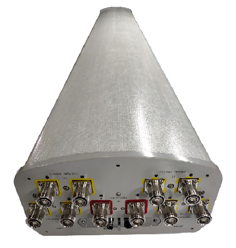
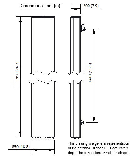
| Dimensions - H x W x D | mm (in) | 1950 x 350 x 200 (76.8 x 13.8 x 7.9) | | Weight (Antenna Only) | kg (lb) | 25 (55.1) | | Weight (Mounting Hardware only) | kg (lb) | 4.5 (9.9) | | Packing size- HxWxD | mm (in) | 2200 x 445 x 295 (86.6 x 17.5 x 11.6) | | Shipping Weight | kg (lb) | 34 (74.9) | | Connector type | | 10 x 4.3-10 female/bottom + 2 AISG connectors (1 male, 1 female) | | Radome Material / Color | | Fiberglass / Light Grey RAL7035 |
|
Testing and Environmental |
|---|
| Temperature Range | °C (°F) | -40 to 60 (-40 to 140 ) | | Lightning protection | | Direct Ground | | Survival/Rated Wind Velocity | km/h | 220 (160 ) | | Wind Load @Rated Wind Front | N | 842 | | Wind Load @Rated Wind Side | N | 413 | | Wind Load @Rated Wind Rear | N | 1025 |
|
Ordering Information |
|---|
| Order No. | Configuration | Mounting Hardware | Mounting Pipe Diameter | Shipping Weight | | APXVB4L20B_43-C-I20 | Internal RET(ACU-I20-B5) | APM50-B1 | 50-110mm | 34.0 kg |
|
Notes
- All electrical parameters are compliant with BASTA NGMN 11.1 requirements.
- For additional mounting information please click "External Document Links".