- Home
- /
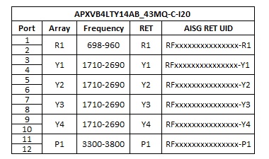
- APXVB4LTY14AB_43MQ-C-I20
APXVB4LTY14AB_43MQ-C-I20
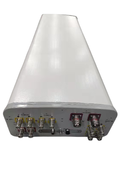
Hybrid FDD/TDD Antenna, X-Pol, 1.4m, 10-ports FDD 1x 698-960/4x 1710-2690MHz, 65deg, 8T8R 3300-3800MHz, 90deg unit beam, MQ4/MQ5 Connectors, Integrated RET, Site Sharing Optional
Rev : J | Rev date : 28 Dec 2023

FEATURES / BENEFITS
- Hybrid FDD + TDD beamforming within a radome
- 2 ports / 1 cross pol system in low band (698-960MHz)
- 8 ports / 4 cross pol systems in high band (1710-2690MHz)
- TDD 8ports + 1 calibration port in 3.5GHz (3300-3800MHz)
- Integrated and field replaceable SRET
- Compliant with AISG V2.0 and 3GPP
Electrical Specifications |
|---|
| Electrical Specification Header | | Low Band Array (698-960 MHz) [R1] |
| Frequency Band |
MHz |
698-806 |
790-894 |
880-960 |
| Gain Typical |
dBi |
14.8 |
14.9 |
15.1 |
| Gain Over all Tilts |
dBi |
14.5+/-0.3 |
14.6+/-0.3 |
14.7+/-0.4 |
| Azimuth Beamwidth 3dB |
Deg |
65.8+/-3.8 |
65.0+/-5.3 |
59.5+/-3.5 |
| Elevation Beamwidth 3dB |
Deg |
17.1+/-1.5 |
15.0+/-1.1 |
13.7+/-0.5 |
| Cross Polar Discrimination at Boresight |
dB |
24.5 |
24.0 |
20.4 |
| Cross Polar Discrimination over Sector |
dB |
9.3 |
9.9 |
9.8 |
| F/B at +/-30deg Total Power |
dB |
21.8 |
23.6 |
22.1 |
| First Upper Side Lobe Suppression |
dB |
11.6 |
11.7 |
11.6 |
| Electrical Downtilt |
Deg |
2 to 14 |
| Cross Polar Isolation |
dB |
25 |
| Interband Isolation |
dB |
25 |
| VSWR |
- |
1.5 |
| Passive Intermodulation (3rd Order, 2 x 43dBm) |
dBc |
-150 |
| Maximum Effective Power per Port |
Watt |
350 |
|
Electrical Specifications |
|---|
| Electrical Specification Header | | High Band Array (1710-2690 MHz) [Y1/Y2/Y3/Y4] |
| Frequency Band |
MHz |
1710-1880 |
1850-1990 |
1920-2170 |
2300-2400 |
2490-2690 |
| Gain Typical |
dBi |
15.1 |
15.2 |
15.4 |
15.0 |
16.0 |
| Gain Over all Tilts |
dBi |
14.5+/-0.6 |
14.7+/-0.5 |
14.8+/-0.6 |
14.4+/-0.6 |
15.4+/-0.6 |
| Azimuth Beamwidth 3dB |
Deg |
69.8+/-5.3 |
66.6+/-3.5 |
66.3+/-4.3 |
62.0+/-4.4 |
54.3+/-4.6 |
| Elevation Beamwidth 3dB |
Deg |
13.7+/-1.0 |
12.6+/-0.9 |
12.1+/-0.9 |
10.9+/-0.5 |
9.9+/-0.8 |
| Cross Polar Discrimination at Boresight |
dB |
21.7 |
21.1 |
20.0 |
19.4 |
22.4 |
| Cross Polar Discrimination over Sector |
dB |
10.0 |
9.4 |
9.1 |
6.8 |
2.9 |
| F/B at +/-30deg Total Power |
dB |
21.8 |
22.3 |
22.7 |
22.6 |
21.7 |
| First Upper Side Lobe Suppression |
dB |
16.1 |
15.5 |
15.8 |
15.4 |
13.4 |
| Electrical Downtilt |
Deg |
2 to 12 |
| Cross Polar Isolation |
dB |
25 |
| Interband Isolation |
dB |
25 |
| VSWR |
- |
1.5 |
| Passive Intermodulation (3rd Order, 2 x 43dBm) |
dBc |
-150 |
| Maximum Effective Power per Port |
Watt |
250 |
|
Electrical Specifications |
|---|
| Electrical Specification Header | | Cal. board and S parameter (3300-3800 MHz) [P1] |
| Frequency Band |
MHz |
3300-3600 |
3600-3800 |
| Coupling between cal. Port to input port |
dB |
-26+/-2 |
| Coupling amplitude accuracy |
dB |
≤ 0.9 |
| Coupling phase accuracy |
deg |
≤ 7 |
| VSWR |
- |
≤ 1.5 |
| Maximum Power |
Watt |
50 |
| ISO co-polor @ 2-6 deg tilt |
dB |
≥ 19 |
| ISO co-polor @ 7-12 deg tilt |
dB |
≥ 25 |
| ISO cross-polor @ 2-6 deg tilt |
dB |
≥ 24 |
| ISO cross-polor @ 7-12 deg tilt |
dB |
≥ 25 |
|
Electrical Specifications |
|---|
| Electrical Specification Header | | Radiation Parameter - Unit Beam (3300-3800 MHz) [P1] |
| Frequency Band |
MHz |
3300-3600 |
3600-3800 |
| Gain Typical |
dBi |
15 |
15 |
| Gain Over all Tilts |
dBi |
14.3+/-0.7 |
14.2+/-0.8 |
| Azimuth Beamwidth 3dB |
Deg |
78.3+/-7.4 |
67.1+/-9.2 |
| Elevation Beamwidth 3dB |
Deg |
9.1+/-1.1 |
8.1+/-0.8 |
| Cross Polar Discrimination at Boresight |
dB |
17.3 |
16.6 |
| Cross Polar Discrimination over Sector |
dB |
9.1 |
8.0 |
| F/B at +/-30deg Total Power |
dB |
18.2 |
17.6 |
| First Upper Side Lobe Suppression |
dB |
15.0 |
15.8 |
| Electrical Downtilt |
Deg |
2 to 12 |
| VSWR |
- |
1.5 |
|
Electrical Specifications |
|---|
| Electrical Specification Header | | Radiation Parameter - Broad casting Beam (3300-3800 MHz) [P1] |
| Frequency Band |
MHz |
3300-3600 |
3600-3800 |
| Gain Typical |
dBi |
15.3 |
16.2 |
| Gain Over all Tilts |
dBi |
14.8 +/- 0.5 |
15.2 +/- 1 |
| Azimuth Beamwidth 3dB |
Deg |
69.5 +/- 6 |
60.1 +/- 6.5 |
| Elevation Beamwidth 3dB |
Deg |
8.4 +/- 1 |
7.8 +/- 0.5 |
| F/B at +/-30deg Total Power |
dB |
21 |
20.3 |
| First Upper Side Lobe Suppression |
dB |
16.7 |
16 |
| Electrical Downtilt |
Deg |
2 to 12 |
| VSWR |
- |
1.5 |
|
Electrical Specifications |
|---|
| Electrical Specification Header | | Radiation Parameter - Working Beam (3300-3800 MHz) [P1] | | Frequency Band | MHz | 3300-3600 | 3600-3800 | | Gain Typical | dBi | 20.4 | 20.2 | | Gain Over all Tilts | dBi | 19.4 +/- 1 | 19.2 +/- 1 | | Azimuth Beamwidth 3dB | Deg | 21.6 +/- 1.3 | 19.9 +/- 1 | | Elevation Beamwidth 3dB | Deg | 8.3 +/- 0.5 | 7.9 +/- 0.7 | | F/B at +/-30deg Total Power | dB | 25 | 25.9 | | First Upper Side Lobe Suppression | dB | 18.7 | 16.6 | | Electrical Downtilt | Deg | 2 to 12 | | VSWR | - | 1.5 |
|
Electrical Specifications |
|---|
| Impedance | Ohm | 50 | | Polarization | Deg | ±45° |
|
Mechanical Specifications |
|---|
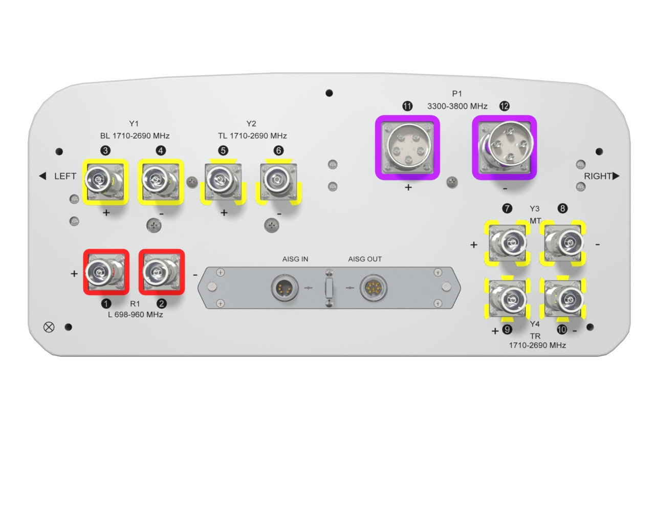
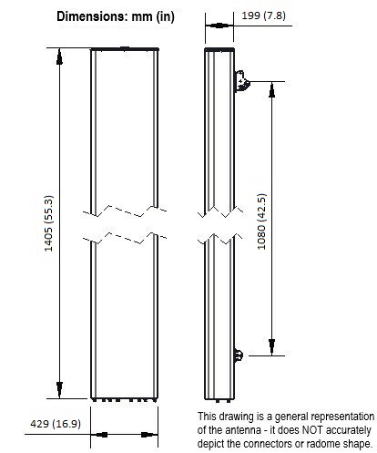
| Dimensions - H x W x D | mm (in) | 1405 x 429 x 199 (55.3 x 16.9 x 7.8) | | Weight (Antenna Only) | kg (lb) | 26.7 (58.9) | | Weight (Mounting Hardware only) | kg (lb) | 4.5 (9.9) | | Packing size- HxWxD | mm (in) | 1675 x 525 x 295 (65.9 x 20.7 x 11.6) | | Shipping Weight | kg (lb) | 37.2 (82) | | Connector type | | 10x 4.3-10 female + 2x Cluster connectors MQ4/MQ5 + 2 AISG connectors (1 male, 1 female) | | Radome Material / Color | | Fiber Glass / Light Grey RAL7035 |
|
Testing and Environmental |
|---|
| Temperature Range | °C (°F) | -40 to 60 (-40 to 140 ) | | Lightning protection | | DC Ground | | Survival/Rated Wind Velocity | km/h | 200 (150 ) | | Wind Load @Rated Wind Front | N | 399 | | Wind Load @Rated Wind Side | N | 404 | | Wind Load @Rated Wind Rear | N | 463 | | Survival wind Velocity | km/h | 200 |
|
Ordering Information |
|---|
| Order No. | Configuration | Mounting Hardware | Mounting pipe Diameter | Shipping Weight | | APXVB4LTY14AB_43MQ-C-I20 | Internal RET (ACU-I20-B6) | APM50-B1 | 50-110mm | 37.2 kg | | APXVB4LTY14AB_43MQ-C-I20S (Material Code: 50016718) | Internal RET (ACU-X20-B6) Dynamic Site Sharing mode | APM50-B1 | 50-110mm | 37.2 kg | | APXVB4LTY14AB_43MQ-C-I20S (Material Code: 50016719) | Internal RET (ACU-X20-B6) Static Site Sharing mode | APM50-B1 | 50-110mm | 37.2 kg |
|
Notes
- All electrical parameters are compliant with BASTA NGMN 11.1 requirements.
- Horizontal dipole column spacing: 55mm.
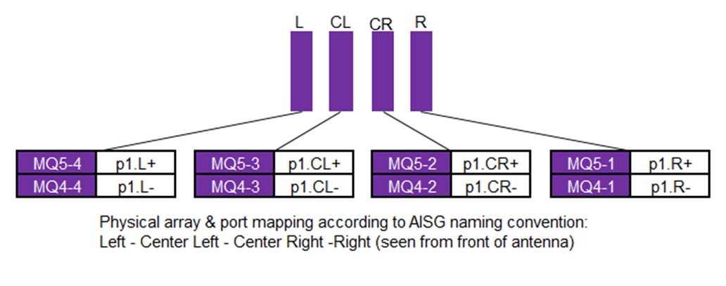
- MQ4/MQ5 cluster connectivity follow NGMN.
- For additional mounting information please click "External Document Links".