
- Home
- /
- Cables & Waveguides
- /
- HYBRIFLEX Optical Fiber & Power Cables
- /
- Hybrid
- /
- Hybrid Assemblies
- /
- HB078-13U3S6-50M2
HB078-13U3S6-50M2
HYBRIFLEX® Hybrid Feeder Cabling Solution 3x6, 6AWG, 7/8”, Single-Mode Fiber, DLC to ODC, with 6AWG DC breakout top, 50 m
PRODUCT DESCRIPTION
RFS Technologies’ HYBRIFLEX Remote Radio Head (RRH) hybrid feeder cabling solution combines optical fiber and DC power for RRHs in a single lightweight aluminum corrugated cable, making it the world’s most innovative solution for RRH deployments. It was developed to reduce installation complexity and costs at Cellular sites.
HYBRIFLEX allows mobile operators deploying an RRH architecture to standardize the RRH installation process. HYBRIFLEX combines optical fiber (multi-mode or single-mode) and power in a single corrugated cable. It may eliminate the need for junction boxes as well as works in conjuction with and can connect multiple RRHs with a single feeder. Standard RFS Technologies CELLFLEX® accessories can be used with HYBRIFLEX cable. Both pre-connectorized and on-site options are available.
FEATURES / BENEFITS
- Aluminum corrugated armor with outstanding bending characteristics – Minimizes installation time and enables mechanical protection and shielding
- Same accessories as 7/8" coaxial cable
- Outer conductor grounding – Utilizes same grounding methods as coaxial cable
- Lightweight solution and compact design – Decreases tower loading
- Robust cabling – Eliminates need for expensive cable trays and ducts
- Installation of tight bundled fiber optic cable pairs directly to the RRH – Reduces CAPEX and wind load by eliminating need for interconnection
- Optical fiber and power cables housed in single corrugated cable – Saves CAPEX by standardizing RRH cable installation and reducing installation requirements
- Outdoor, black PE jacket – Ensures long-lasting cable protection
- Shielded DC wire – Jacketed and braided cable on top breakout provides grounding and EMI protection
- Maximum robustness – Fully armored cable includes riser trunk and top outdoor breakout

TECHNICAL FEATURES
|
|||||||||
| ||||||
|
||||||||||||||||||
|
||||||||||||
|
|||||||||
|
|||||||||||||||||||||||||||||||||
|
|||||||||||||||||||||||||||||||||||||||
|
||||||||||||
|
||||||
|
||||||
EXTERNAL DOCUMENT LINKS
Installation Guidelines: Download
On-line Factory Test Results: View
NOTES
Nominal length equals length of trunk not including top and bottom breakouts; breakout lengths add additionally to the total assembly length tip to tip.
Top Breakout - DC Power Cable Specifications:
- No of DC pairs 3; Specifications per 1 pair:
- Maximum DC-Resistance Power Cable Ω/km (Ω/ft) 1.4 (0.42)
- Cross Section of Power Cable mm2 (AWG) 13.3 (6)
- Overall Cable Diameter mm (in) 17.8 (0.708)
- DC Cable Jacket Material PVC
- EMI Shield Tinned Copper Braid
|
||||||||||||||||||||||||||||||

Related Products
GKFORM60-78
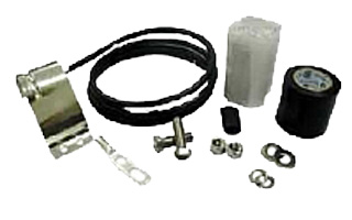
Grounding Kit, Pre-formed Copper Strap, 1.5m (60") for CELLFLEX® 7/8" Cable
- Type of Grounding Kit : Pre-Formed Copper Strap
- Package Quantity : 1
- Weight per piece, kg (lb) : 0.3 (0.66)
Wall Feedthrough Sealing
Feed through assemblies for 7/8" coaxial cable, 102mm (4"), 1-entry
Feed through assemblies for 7/8" coaxial cable, 102mm (4"), 2-entries
Feed through assemblies for 7/8" coaxial cable, 102mm (4"), 3-entries
Feed through assemblies for 7/8" coaxial cable, 102mm (4"), 4-entries
Wall feed through (without feed through plate)
Tools
Stripping tool for high speed grounding kit GKSPEED-78 series
Hand tool kit for the installation of connectors and grounding kits on CELLFLEX® Cables
Hoisting Grip for Coaxial Cable and Elliptical Waveguide, Closed Lacing
Hoisting Grip for Coaxial Cable and Elliptical Waveguide, Lace-Up
Automated trimming tool, LCF78, UCF 78, OMNI FIT Premium, Trim Series D01
Flaring Tool LCF 7/8" for Universal Trimming Tools
Clamps
Double Multi-block hanger three layers, with angle member adapter
Double Multi-block hanger one layer, with angle member adapter
Single Multi-block hanger one layer, with angle member adapter
Single Multi-block hanger two layer, with angle member adapter
Single Multi-block hanger three layer, with angle member adapter
Cable hanger, non-insulated, bolt-on, for 7/8" coaxial cable and E100, E105 elliptical waveguide
Snap-In Hangers, 7/8", stainless steel (kit of 10)
Stackable Snap-In Hangers, 7/8", stainless steel (kit of 10)
Grounding Kit
High speed grounding kit for CELLFLEX® LCF 78
Connectors
4.3-10 Female Connector for 1/2" Coaxial Cable, OMNI FIT™ standard, O-ring sealing
N Male Connector for 7/8" Coaxial Cable, OMNI FIT™ Premium,
Straight, O-Ring and compression sealing
N Female Connector for 7/8" Coaxial Cable, OMNI FIT™ Premium,
Straight, O-Ring and compression sealing
7-16 DIN Male Connector for 7/8" Coaxial Cable, OMNI FIT™ Premium,
Right Angle, O-Ring and compression sealing
7-16 DIN Male Connector for 7/8" Coaxial Cable, OMNI FIT™ Premium,
Straight, O-Ring and compression sealing
7-16 DIN Female Connector for 7/8" Coaxial Cable, OMNI FIT™ Premium, Straight, O-Ring and compression sealing
4.3-10 Male Straight Connector for 7/8" Coaxial Cable, OMNI FIT™ Premium, Polymer claw and compression sealing
4.3-10 Female Straight Connector for 7/8" Coaxial Cable, OMNI FIT™ Premium, Polymer claw and compression sealing
N Male Connector for 7/8" Coaxial Cable, OMNI FIT™ standard, O-ring sealing
7-16 DIN Female Connector for 7/8" Coaxial Cable, OMNI FIT™ standard, O-ring sealing
N Male Connector for 7/8" Coaxial Cable, OMNI FIT™ standard, O-ring sealing
N Female Connector for 7/8" Coaxial Cable, OMNI FIT™ standard, O-ring sealing
7-16 Male Connector for 7/8" Coaxial Cable, OMNI FIT™ standard, O-ring sealing
7-16 DIN Female Connector for 7/8" Coaxial Cable, OMNI FIT™ standard, O-ring sealing
4.3-10 Male Push-Pull Connector for 7/8" Coaxial Cable, OMNI FIT™ standard, O-ring sealing
4.3-10 Male Connector for 7/8" Coaxial Cable, OMNI FIT™ standard, O-ring sealing
4.3-10 Male Hand-Screw Connector for 7/8" Coaxial Cable, OMNI FIT™ standard, O-ring sealing
4.3-10 Female Connector for 7/8" Coaxial Cable, OMNI FIT™ standard, O-ring sealing
7-16 DIN Male Connector for 7/8" Coaxial Cable, OMNI FIT™ Premium,
Straight, O-Ring and compression sealing
7-16 DIN Female Connector for 7/8" Coaxial Cable, OMNI FIT™ Premium, Straight, O-Ring and compression sealing
N Male Connector for 7/8" Coaxial Cable, OMNI FIT™ Premium,
Straight, O-Ring and 360° compression sealing
N Female Connector for 7/8" Coaxial Cable, OMNI FIT™ Premium,
Straight, O-Ring and 360° compression sealing
Coaxial Transmission Line
7/8" CELLFLEX® Lite Low-Loss Foam-Dielectric Coaxial Cable
7/8" CELLFLEX® Premium Attenuation Low-Loss Foam-Dielectric Coaxial Cable
7/8" CELLFLEX® Lite Low-Loss Foam-Dielectric Coaxial Cable
7/8" CELLFLEX® Premium Attenuation Low-Loss Foam-Dielectric Coaxial Cable
7/8" CELLFLEX® Premium Attenuation Low-Loss Foam-Dielectric Coaxial Cable
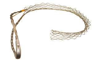
HOIST1-78L
Hoisting Grip for Coaxial Cable and Elliptical Waveguide, Lace-Up
- Product Line : Coaxial Cable Accessories, Elliptical Waveguide Accessories
- Product Type : Hoisting Grip
Clamps
Cable hanger for Air Dielectric Cable
Cable hanger for Air Dielectric Cable
Cable hanger for Air Dielectric Cable
RSB Clip with clamp lining for FLEXWELL® Elliptical Waveguide E105
Double Multi-block hanger three layers, with angle member adapter
Double Multi-block hanger one layer, with angle member adapter
Single Multi-block hanger one layer, with angle member adapter
Single Multi-block hanger two layer, with angle member adapter
Single Multi-block hanger three layer, with angle member adapter
Cable hanger, non-insulated, bolt-on, for 7/8" coaxial cable and E100, E105 elliptical waveguide
Snap-In Hangers, 7/8", stainless steel (kit of 10)
Stackable Snap-In Hangers, 7/8", stainless steel (kit of 10)
Wall Feedthrough Sealing
Feed through assemblies for 7/8" coaxial cable, 102mm (4"), 1-entry
Feed through assemblies for 7/8" coaxial cable, 102mm (4"), 2-entries
Feed through assemblies for 7/8" coaxial cable, 102mm (4"), 3-entries
Feed through assemblies for 7/8" coaxial cable, 102mm (4"), 4-entries
Wall/Roof Feedthrough E105/EP105
Wall feed through (without feed through plate)
4" Feed Through Boot Assembly w/1 hole for E105
Wall Feed Thru for FLEXWELL® Elliptical Waveguide E105 and EO19
Coaxial Transmission Line
7/8" Air Dielectric Cable, flame retardant/ halogen free jacket
7/8" Air Dielectric Cable
7/8" Air Dielectric Cable
7/8" CELLFLEX® Lite Low-Loss Foam-Dielectric Coaxial Cable
7/8" CELLFLEX® Premium Attenuation Low-Loss Foam-Dielectric Coaxial Cable
7/8" CELLFLEX® Lite Low-Loss Foam-Dielectric Coaxial Cable
7/8" CELLFLEX® Premium Attenuation Low-Loss Foam-Dielectric Coaxial Cable
7/8" CELLFLEX® Premium Attenuation Low-Loss Foam-Dielectric Coaxial Cable
Tools
Stripping tool for high speed grounding kit GKSPEED-78 series
Hand tool kit for the installation of connectors and grounding kits on CELLFLEX® Cables
Hoisting Grip for Coaxial Cable and Elliptical Waveguide, Closed Lacing
Compact tool for E105 to E380
Automated trimming tool, LCF78, UCF 78, OMNI FIT Premium, Trim Series D01
Flanging die for use with FLEXWELL® waveguide E105, compact tool
Flanging die for use with FLEXWELL® waveguide E105, basic tool
Basic tool for E38 to E130
Flaring Tool LCF 7/8" for Universal Trimming Tools
Grounding Kit
Grounding Kit, Pre-formed Copper Strap, for E105
High speed grounding kit for CELLFLEX® LCF 78
Grounding Kit, Pre-formed Copper Strap, 1.5m (60") for CELLFLEX® 7/8" Cable
Grounding Kit, Pre-formed Copper Strap, for E105
Grounding kit for FLEXWELL® Elliptical Waveguide E105
Grounding kit for FLEXWELL® Elliptical Waveguide E100
Connectors
7-16 DIN Female Connector for 7/8" Coaxial Cable, RAPID FIT™ Sealing compound
7-16 DIN Male Connector for 7/8" Coaxial Cable, RAPID FIT™ Sealing compound
7/8" EIA Connector for 7/8" Coaxial Cable, Gas pass, Sealing compound
7/8" EIA Female Connector for 7/8" Coaxial Cable, RAPID FIT™ Sealing compound
N Female Connector for 7/8" Coaxial Cable, RAPID FIT™ Sealing compound
N Male Connector for 7/8" Coaxial Cable, RAPID FIT™ Sealing compound
4.3-10 Female Connector for 1/2" Coaxial Cable, OMNI FIT™ standard, O-ring sealing
N Male Connector for 7/8" Coaxial Cable, OMNI FIT™ Premium,
Straight, O-Ring and compression sealing
N Female Connector for 7/8" Coaxial Cable, OMNI FIT™ Premium,
Straight, O-Ring and compression sealing
7-16 DIN Male Connector for 7/8" Coaxial Cable, OMNI FIT™ Premium,
Right Angle, O-Ring and compression sealing
7-16 DIN Male Connector for 7/8" Coaxial Cable, OMNI FIT™ Premium,
Straight, O-Ring and compression sealing
7-16 DIN Female Connector for 7/8" Coaxial Cable, OMNI FIT™ Premium, Straight, O-Ring and compression sealing
4.3-10 Male Straight Connector for 7/8" Coaxial Cable, OMNI FIT™ Premium, Polymer claw and compression sealing
4.3-10 Female Straight Connector for 7/8" Coaxial Cable, OMNI FIT™ Premium, Polymer claw and compression sealing
N Male Connector for 7/8" Coaxial Cable, OMNI FIT™ standard, O-ring sealing
7-16 DIN Female Connector for 7/8" Coaxial Cable, OMNI FIT™ standard, O-ring sealing
N Male Connector for 7/8" Coaxial Cable, OMNI FIT™ standard, O-ring sealing
N Female Connector for 7/8" Coaxial Cable, OMNI FIT™ standard, O-ring sealing
7-16 Male Connector for 7/8" Coaxial Cable, OMNI FIT™ standard, O-ring sealing
7-16 DIN Female Connector for 7/8" Coaxial Cable, OMNI FIT™ standard, O-ring sealing
4.3-10 Male Push-Pull Connector for 7/8" Coaxial Cable, OMNI FIT™ standard, O-ring sealing
4.3-10 Male Connector for 7/8" Coaxial Cable, OMNI FIT™ standard, O-ring sealing
4.3-10 Male Hand-Screw Connector for 7/8" Coaxial Cable, OMNI FIT™ standard, O-ring sealing
4.3-10 Female Connector for 7/8" Coaxial Cable, OMNI FIT™ standard, O-ring sealing
7-16 DIN Male Connector for 7/8" Coaxial Cable, OMNI FIT™ Premium,
Straight, O-Ring and compression sealing
7-16 DIN Female Connector for 7/8" Coaxial Cable, OMNI FIT™ Premium, Straight, O-Ring and compression sealing
N Male Connector for 7/8" Coaxial Cable, OMNI FIT™ Premium,
Straight, O-Ring and 360° compression sealing
N Female Connector for 7/8" Coaxial Cable, OMNI FIT™ Premium,
Straight, O-Ring and 360° compression sealing
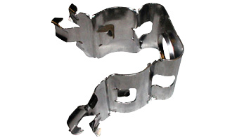
SNAP-78
Snap-In Hangers, 7/8", stainless steel (kit of 10)
- Hanger Type : Snap-in
- Cable Type : Coaxial Foam Dielectric, Superflexible Coaxial Foam Dielectric, Ultraflexible Coaxial Foam Dielectric , Air Dielectric, Hybrid
- Cable Size : 7/8
Installation Hardware
Universal angle adapter, Snap-in or 3/8" (kit of 10)
Wall Feedthrough Sealing
Feed through assemblies for 7/8" coaxial cable, 102mm (4"), 1-entry
Feed through assemblies for 7/8" coaxial cable, 102mm (4"), 2-entries
Feed through assemblies for 7/8" coaxial cable, 102mm (4"), 3-entries
Feed through assemblies for 7/8" coaxial cable, 102mm (4"), 4-entries
Wall feed through (without feed through plate)
Tools
Stripping tool for high speed grounding kit GKSPEED-78 series
Hand tool kit for the installation of connectors and grounding kits on CELLFLEX® Cables
Hoisting Grip for Coaxial Cable and Elliptical Waveguide, Closed Lacing
Hoisting Grip for Coaxial Cable and Elliptical Waveguide, Lace-Up
Automated trimming tool, LCF78, UCF 78, OMNI FIT Premium, Trim Series D01
Flaring Tool LCF 7/8" for Universal Trimming Tools
Clamps
Double Multi-block hanger three layers, with angle member adapter
Double Multi-block hanger one layer, with angle member adapter
Single Multi-block hanger one layer, with angle member adapter
Single Multi-block hanger two layer, with angle member adapter
Single Multi-block hanger three layer, with angle member adapter
Cable hanger, non-insulated, bolt-on, for 7/8" coaxial cable and E100, E105 elliptical waveguide
Snap-In Hangers, 1-1/4", stainless steel (kit of 10)
Snap-In Hangers, 1/2", stainless steel (kit of 10)
Snap-In Hangers, 5/8", stainless steel (kit of 10)
Stackable Snap-In Hangers, 1-5/8", stainless steel (kit of 10)
Stackable Snap-In Hangers, 1/2", stainless steel (kit of 10)
Stackable Snap-In Hangers, 1-1/4", stainless steel (kit of 10)
Stackable Snap-In Hangers, 7/8", stainless steel (kit of 10)
Snap-In Hangers, 1-5/8", stainless steel (kit of 10)
Grounding Kit
High speed grounding kit for CELLFLEX® LCF 78
Grounding Kit, Pre-formed Copper Strap, 1.5m (60") for CELLFLEX® 7/8" Cable
Connectors
4.3-10 Female Connector for 1/2" Coaxial Cable, OMNI FIT™ standard, O-ring sealing
N Male Connector for 7/8" Coaxial Cable, OMNI FIT™ Premium,
Straight, O-Ring and compression sealing
N Female Connector for 7/8" Coaxial Cable, OMNI FIT™ Premium,
Straight, O-Ring and compression sealing
7-16 DIN Male Connector for 7/8" Coaxial Cable, OMNI FIT™ Premium,
Right Angle, O-Ring and compression sealing
7-16 DIN Male Connector for 7/8" Coaxial Cable, OMNI FIT™ Premium,
Straight, O-Ring and compression sealing
7-16 DIN Female Connector for 7/8" Coaxial Cable, OMNI FIT™ Premium, Straight, O-Ring and compression sealing
4.3-10 Male Straight Connector for 7/8" Coaxial Cable, OMNI FIT™ Premium, Polymer claw and compression sealing
4.3-10 Female Straight Connector for 7/8" Coaxial Cable, OMNI FIT™ Premium, Polymer claw and compression sealing
N Male Connector for 7/8" Coaxial Cable, OMNI FIT™ standard, O-ring sealing
7-16 DIN Female Connector for 7/8" Coaxial Cable, OMNI FIT™ standard, O-ring sealing
N Male Connector for 7/8" Coaxial Cable, OMNI FIT™ standard, O-ring sealing
N Female Connector for 7/8" Coaxial Cable, OMNI FIT™ standard, O-ring sealing
7-16 Male Connector for 7/8" Coaxial Cable, OMNI FIT™ standard, O-ring sealing
7-16 DIN Female Connector for 7/8" Coaxial Cable, OMNI FIT™ standard, O-ring sealing
4.3-10 Male Push-Pull Connector for 7/8" Coaxial Cable, OMNI FIT™ standard, O-ring sealing
4.3-10 Male Connector for 7/8" Coaxial Cable, OMNI FIT™ standard, O-ring sealing
4.3-10 Male Hand-Screw Connector for 7/8" Coaxial Cable, OMNI FIT™ standard, O-ring sealing
4.3-10 Female Connector for 7/8" Coaxial Cable, OMNI FIT™ standard, O-ring sealing
7-16 DIN Male Connector for 7/8" Coaxial Cable, OMNI FIT™ Premium,
Straight, O-Ring and compression sealing
7-16 DIN Female Connector for 7/8" Coaxial Cable, OMNI FIT™ Premium, Straight, O-Ring and compression sealing
N Male Connector for 7/8" Coaxial Cable, OMNI FIT™ Premium,
Straight, O-Ring and 360° compression sealing
N Female Connector for 7/8" Coaxial Cable, OMNI FIT™ Premium,
Straight, O-Ring and 360° compression sealing
Coaxial Transmission Line
7/8" CELLFLEX® Lite Low-Loss Foam-Dielectric Coaxial Cable
7/8" CELLFLEX® Premium Attenuation Low-Loss Foam-Dielectric Coaxial Cable
7/8" CELLFLEX® Lite Low-Loss Foam-Dielectric Coaxial Cable
7/8" CELLFLEX® Premium Attenuation Low-Loss Foam-Dielectric Coaxial Cable
7/8" CELLFLEX® Premium Attenuation Low-Loss Foam-Dielectric Coaxial Cable
SNAP-ST-78
Stackable Snap-In Hangers, 7/8", stainless steel (kit of 10)
- Hanger Type : Stackable
- Cable Type : Coaxial Foam Dielectric, Hybrid
- Cable Size : 7/8
Installation Hardware
Universal angle adapter, Snap-in or 3/8" (kit of 10)
Wall Feedthrough Sealing
Feed through assemblies for 7/8" coaxial cable, 102mm (4"), 1-entry
Feed through assemblies for 7/8" coaxial cable, 102mm (4"), 2-entries
Feed through assemblies for 7/8" coaxial cable, 102mm (4"), 3-entries
Feed through assemblies for 7/8" coaxial cable, 102mm (4"), 4-entries
Wall feed through (without feed through plate)
Tools
Stripping tool for high speed grounding kit GKSPEED-78 series
Hand tool kit for the installation of connectors and grounding kits on CELLFLEX® Cables
Hoisting Grip for Coaxial Cable and Elliptical Waveguide, Closed Lacing
Hoisting Grip for Coaxial Cable and Elliptical Waveguide, Lace-Up
Automated trimming tool, LCF78, UCF 78, OMNI FIT Premium, Trim Series D01
Flaring Tool LCF 7/8" for Universal Trimming Tools
Clamps
Double Multi-block hanger three layers, with angle member adapter
Double Multi-block hanger one layer, with angle member adapter
Single Multi-block hanger one layer, with angle member adapter
Single Multi-block hanger two layer, with angle member adapter
Single Multi-block hanger three layer, with angle member adapter
Cable hanger, non-insulated, bolt-on, for 7/8" coaxial cable and E100, E105 elliptical waveguide
Snap-In Hangers, 1-1/4", stainless steel (kit of 10)
Snap-In Hangers, 1/2", stainless steel (kit of 10)
Snap-In Hangers, 5/8", stainless steel (kit of 10)
Snap-In Hangers, 7/8", stainless steel (kit of 10)
Stackable Snap-In Hangers, 1-5/8", stainless steel (kit of 10)
Stackable Snap-In Hangers, 1/2", stainless steel (kit of 10)
Stackable Snap-In Hangers, 1-1/4", stainless steel (kit of 10)
Snap-In Hangers, 1-5/8", stainless steel (kit of 10)
Grounding Kit
High speed grounding kit for CELLFLEX® LCF 78
Grounding Kit, Pre-formed Copper Strap, 1.5m (60") for CELLFLEX® 7/8" Cable
Connectors
4.3-10 Female Connector for 1/2" Coaxial Cable, OMNI FIT™ standard, O-ring sealing
N Male Connector for 7/8" Coaxial Cable, OMNI FIT™ Premium,
Straight, O-Ring and compression sealing
N Female Connector for 7/8" Coaxial Cable, OMNI FIT™ Premium,
Straight, O-Ring and compression sealing
7-16 DIN Male Connector for 7/8" Coaxial Cable, OMNI FIT™ Premium,
Right Angle, O-Ring and compression sealing
7-16 DIN Male Connector for 7/8" Coaxial Cable, OMNI FIT™ Premium,
Straight, O-Ring and compression sealing
7-16 DIN Female Connector for 7/8" Coaxial Cable, OMNI FIT™ Premium, Straight, O-Ring and compression sealing
4.3-10 Male Straight Connector for 7/8" Coaxial Cable, OMNI FIT™ Premium, Polymer claw and compression sealing
4.3-10 Female Straight Connector for 7/8" Coaxial Cable, OMNI FIT™ Premium, Polymer claw and compression sealing
N Male Connector for 7/8" Coaxial Cable, OMNI FIT™ standard, O-ring sealing
7-16 DIN Female Connector for 7/8" Coaxial Cable, OMNI FIT™ standard, O-ring sealing
N Male Connector for 7/8" Coaxial Cable, OMNI FIT™ standard, O-ring sealing
N Female Connector for 7/8" Coaxial Cable, OMNI FIT™ standard, O-ring sealing
7-16 Male Connector for 7/8" Coaxial Cable, OMNI FIT™ standard, O-ring sealing
7-16 DIN Female Connector for 7/8" Coaxial Cable, OMNI FIT™ standard, O-ring sealing
4.3-10 Male Push-Pull Connector for 7/8" Coaxial Cable, OMNI FIT™ standard, O-ring sealing
4.3-10 Male Connector for 7/8" Coaxial Cable, OMNI FIT™ standard, O-ring sealing
4.3-10 Male Hand-Screw Connector for 7/8" Coaxial Cable, OMNI FIT™ standard, O-ring sealing
4.3-10 Female Connector for 7/8" Coaxial Cable, OMNI FIT™ standard, O-ring sealing
7-16 DIN Male Connector for 7/8" Coaxial Cable, OMNI FIT™ Premium,
Straight, O-Ring and compression sealing
7-16 DIN Female Connector for 7/8" Coaxial Cable, OMNI FIT™ Premium, Straight, O-Ring and compression sealing
N Male Connector for 7/8" Coaxial Cable, OMNI FIT™ Premium,
Straight, O-Ring and 360° compression sealing
N Female Connector for 7/8" Coaxial Cable, OMNI FIT™ Premium,
Straight, O-Ring and 360° compression sealing
Coaxial Transmission Line
7/8" CELLFLEX® Lite Low-Loss Foam-Dielectric Coaxial Cable
7/8" CELLFLEX® Premium Attenuation Low-Loss Foam-Dielectric Coaxial Cable
7/8" CELLFLEX® Lite Low-Loss Foam-Dielectric Coaxial Cable
7/8" CELLFLEX® Premium Attenuation Low-Loss Foam-Dielectric Coaxial Cable
7/8" CELLFLEX® Premium Attenuation Low-Loss Foam-Dielectric Coaxial Cable
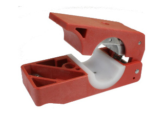
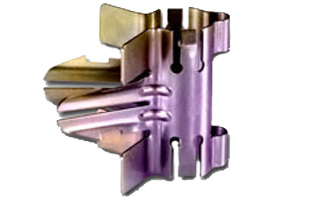
TRIM-SET-H78-001
HYBRIFLEX® Jacket and Armor cutting tool, 7/8"
- Weight, kg (lb) :
- Cable Size : 7/8''
- Type of tool : Combination Cable Cutting Tool
Tools
Manual Jacket Stripping Tool
Stripping tool for high speed grounding kit GKSPEED-114 series
Stripping tool for high speed grounding kit GKSPEED-12 series
Stripping tool for high speed grounding kit GKSPEED-78 series
Stripping tool for high speed grounding kit GKSPEED-158 series
Spare Main Blade for Universal Trimming Tool for cable sizes 1/4" to 7/8"
Hybriflex Tools
HYBRIFLEX® Jacket and Armor cutting tool, 5/8"

HTRT-1-000
HYBRIFLEX® Rip Tool
- Weight, kg (lb) :
- Cable Size : All
- Type of tool : Rip Cord Removal Tool
Tools
Manual Jacket Stripping Tool
Stripping tool for high speed grounding kit GKSPEED-114 series
Stripping tool for high speed grounding kit GKSPEED-12 series
Stripping tool for high speed grounding kit GKSPEED-78 series
Stripping tool for high speed grounding kit GKSPEED-158 series
Spare Main Blade for Universal Trimming Tool for cable sizes 1/4" to 7/8"
Hybriflex Tools
HYBRIFLEX® Jacket and Armor cutting tool, 5/8"
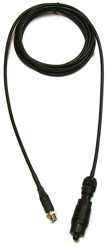
HA-FOJBF-OA-01SM-xx Series
HYBRIFLEX® Optical Fiber Cabling Solution, 1 Pair Armored Bend-Insensitive Single-Mode Fiber with ODC to LC/FullAXS Compatible Connectors
- Length,m (ft) :
- F/O Cable Type : G657-A1 Single Mode, Bend Tolerant
- Number of F/O Pairs : 1
- Fiber Termination End 1 : ODC socket
- Fiber Termination End 2 : DLC Connector with FullAXS Compatibility
Clamps
Snap-In Hangers, 1/2", stainless steel (kit of 10)
Snap-In Hangers, 7/8", stainless steel (kit of 10)
Stackable Snap-In Hangers, 1/2", stainless steel (kit of 10)
Stackable Snap-In Hangers, 7/8", stainless steel (kit of 10)
FPS-HB158-21U6S24-xxM Series
HYBRIFLEX® Hybrid Feeder Cabling Solution 6x24, 4AWG, 1-5/8”, Single-Mode Fiber, DLC to ODC, with 6AWG DC breakout top
FPS-HB114-13U6S12-xxM-01 Series
HYBRIFLEX® Hybrid Feeder Cabling Solution 6x12, 6AWG, 1-1/4”, Single-Mode Fiber, DLC to ODC, with 10AWG DC breakout top
FPS-HB158-21U6S12-xxM-01 Series
HYBRIFLEX® Hybrid Feeder Cabling Solution 6x12, 4AWG, 1-5/8”, Single-Mode Fiber, DLC to ODC, with 10AWG DC breakout top