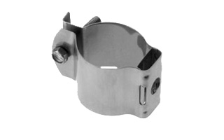
Clamps
Cable hanger, non-insulated, bolt-on, for E60 elliptical waveguide
Cable hanger, non-insulated, bolt-on, for E78 elliptical waveguide
Cable hanger, non-insulated, bolt-on, for 1 1/4" coaxial cable and eliptical waveguide E65 and E70
Cable hanger, non-insulated, bolt-on, for E130 and E150 elliptical waveguide
Cable hanger for Air Dielectric Cable
Cable hanger for Air Dielectric Cable
Cable hanger for Air Dielectric Cable
Cable hanger, non-insulated, bolt-on, for 2 1/4" coaxial cable
Cable hanger, non-insulated, bolt-on, for 3" coaxial cable
Cable hanger, non-insulated, bolt-on, for 4" coaxial cable
Cable hanger, non-insulated, bolt-on, for 1 5/8" coaxial cable
RSB Clip with clamp lining for FLEXWELL® Elliptical Waveguide E105
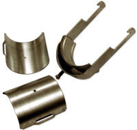
Universal clamp with clamp lining for FLEXWELL® Elliptical Waveguide E78
Universal clamp with clamp lining for FLEXWELL® Elliptical Waveguide E65
Universal clamp with clamp lining for FLEXWELL® Elliptical Waveguide E60
Double Multi-block hanger three layers, with angle member adapter
Double Multi-block hanger one layer, with angle member adapter
Single Multi-block hanger one layer, with angle member adapter
Single Multi-block hanger two layer, with angle member adapter
Single Multi-block hanger three layer, with angle member adapter
Cable hanger with clamp lining for twistflex R70
Cable hanger with clamp lining for twistflex R140
Cable hanger with clamp lining for twistflex R120
Cable hanger with clamp lining for twistflex R100
Cable hanger with clamp lining for twistflex R84
Cable hanger, non-insulated, bolt-on, for 5" coaxial cable
Clic clamp for RADIAFLEX® 7/8"
Snap-In Hangers, 7/8", stainless steel (kit of 10)
Stackable Snap-In Hangers, 7/8", stainless steel (kit of 10)
SFS clamp for RADIAFLEX® 7/8"
Cable hanger, non-insulated, bolt-on, for 1/2" coaxial cable and elliptical waveguide
Installation Hardware
Angle Member Adapter Kit 3/8" (SS) (Kit of 10)
Ceiling adapter, 305mm (12") (kit of 5), 3/8"
Ceiling adapter, 610mm (24") (kit of 5), 3/8"
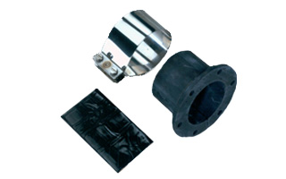
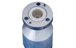
Wall Feedthrough Sealing
Feed through assemblies for 7/8" coaxial cable, 102mm (4"), 1-entry
Feed through assemblies for 7/8" coaxial cable, 102mm (4"), 2-entries
Feed through assemblies for 7/8" coaxial cable, 102mm (4"), 3-entries
Feed through assemblies for 7/8" coaxial cable, 102mm (4"), 4-entries
Wall/Roof Feedthrough E105/EP105
Wall feed through (without feed through plate)
4" Feed Through Boot Assembly w/1 hole for E105
Wall Feed Thru for FLEXWELL® Elliptical Waveguide E105 and EO19
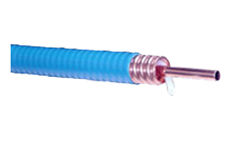
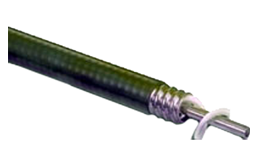
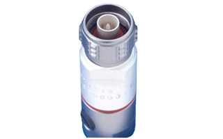
Coaxial Transmission Line
7/8" Air Dielectric Cable, flame retardant/ halogen free jacket
7/8" Air Dielectric Cable
7/8" Air Dielectric Cable
7/8" CELLFLEX® Premium Attenuation Low-Loss Foam-Dielectric Coaxial Cable
7/8" CELLFLEX® Premium Attenuation Low-Loss Foam-Dielectric Coaxial Cable
7/8" CELLFLEX® Premium Attenuation Low-Loss Foam-Dielectric Coaxial Cable
Tools
Stripping tool for high speed grounding kit GKSPEED-78 series
Hand tool kit for the installation of connectors and grounding kits on CELLFLEX® Cables
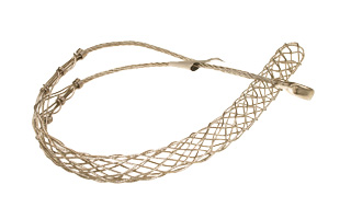
Hoisting Grip for Coaxial Cable and Elliptical Waveguide, Closed Lacing
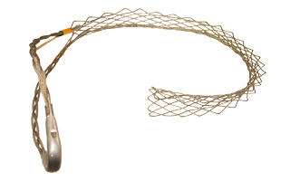
Hoisting Grip for Coaxial Cable and Elliptical Waveguide, Lace-Up
Compact tool for E105 to E380
Automated trimming tool, LCF78, UCF 78, OMNI FIT Premium, Trim Series D01
Flanging die for use with FLEXWELL® waveguide E105, compact tool
Flanging die for use with FLEXWELL® waveguide E105, basic tool
Basic tool for E38 to E130
Flaring Tool LCF 7/8" for Universal Trimming Tools
Grounding Kit
Grounding Kit, Pre-formed Copper Strap, for E105
High speed grounding kit for CELLFLEX® LCF 78
Grounding Kit, Pre-formed Copper Strap, 1.5m (60") for CELLFLEX® 7/8" Cable
Grounding Kit, Pre-formed Copper Strap, for E105
Grounding kit for FLEXWELL® Elliptical Waveguide E105
Grounding kit for FLEXWELL® Elliptical Waveguide E100
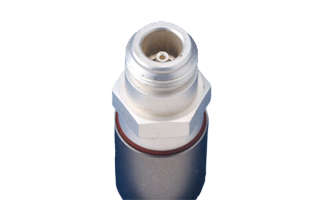
Connectors
7-16 DIN Female Connector for 7/8" Coaxial Cable, RAPID FIT™ Sealing compound
7-16 DIN Male Connector for 7/8" Coaxial Cable, RAPID FIT™ Sealing compound
7/8" EIA Connector for 7/8" Coaxial Cable, Gas pass, Sealing compound
7/8" EIA Female Connector for 7/8" Coaxial Cable, RAPID FIT™ Sealing compound
N Female Connector for 7/8" Coaxial Cable, RAPID FIT™ Sealing compound
N Male Connector for 7/8" Coaxial Cable, RAPID FIT™ Sealing compound
4.3-10 Female Connector for 1/2" Coaxial Cable, OMNI FIT™ standard, O-ring sealing
N Male Connector for 7/8" Coaxial Cable, OMNI FIT™ Premium,
Straight, O-Ring and compression sealing
N Female Connector for 7/8" Coaxial Cable, OMNI FIT™ Premium,
Straight, O-Ring and compression sealing
7-16 DIN Male Connector for 7/8" Coaxial Cable, OMNI FIT™ Premium,
Right Angle, O-Ring and compression sealing
7-16 DIN Male Connector for 7/8" Coaxial Cable, OMNI FIT™ Premium,
Straight, O-Ring and compression sealing
7-16 DIN Female Connector for 7/8" Coaxial Cable, OMNI FIT™ Premium, Straight, O-Ring and compression sealing
4.3-10 Male Straight Connector for 7/8" Coaxial Cable, OMNI FIT™ Premium, Polymer claw and compression sealing
4.3-10 Female Straight Connector for 7/8" Coaxial Cable, OMNI FIT™ Premium, Polymer claw and compression sealing
N Male Connector for 7/8" Coaxial Cable, OMNI FIT™ standard, O-ring sealing
7-16 DIN Female Connector for 7/8" Coaxial Cable, OMNI FIT™ standard, O-ring sealing
N Male Connector for 7/8" Coaxial Cable, OMNI FIT™ standard, O-ring sealing
N Female Connector for 7/8" Coaxial Cable, OMNI FIT™ standard, O-ring sealing
7-16 Male Connector for 7/8" Coaxial Cable, OMNI FIT™ standard, O-ring sealing
7-16 DIN Female Connector for 7/8" Coaxial Cable, OMNI FIT™ standard, O-ring sealing
4.3-10 Male Push-Pull Connector for 7/8" Coaxial Cable, OMNI FIT™ standard, O-ring sealing
4.3-10 Male Connector for 7/8" Coaxial Cable, OMNI FIT™ standard, O-ring sealing
4.3-10 Male Hand-Screw Connector for 7/8" Coaxial Cable, OMNI FIT™ standard, O-ring sealing
4.3-10 Female Connector for 7/8" Coaxial Cable, OMNI FIT™ standard, O-ring sealing
7-16 DIN Male Connector for 7/8" Coaxial Cable, OMNI FIT™ Premium,
Straight, O-Ring and compression sealing
7-16 DIN Female Connector for 7/8" Coaxial Cable, OMNI FIT™ Premium, Straight, O-Ring and compression sealing
N Male Connector for 7/8" Coaxial Cable, OMNI FIT™ Premium,
Straight, O-Ring and 360° compression sealing
N Female Connector for 7/8" Coaxial Cable, OMNI FIT™ Premium,
Straight, O-Ring and 360° compression sealing