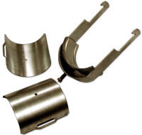
Clamps
Cable hanger, non-insulated, bolt-on, for 1 1/4" coaxial cable and eliptical waveguide E65 and E70
Cable hanger for Air Dielectric Cable
Cable hanger for Air Dielectric Cable
Cable hanger for Air Dielectric Cable
Cable hanger, non-insulated, bolt-on, for 1 5/8" coaxial cable
Single Multi-block hanger, with angle member adapter
Single Multi-block hanger, with angle member adapter
Double Multi-block hanger three layers, with angle member adapter
Double Multi-block hanger one layer, with angle member adapter
Single Multi-block hanger, with angle member adapter
Single Multi-block hanger, with angle member adapter
Single Multi-block hanger, with angle member adapter
Single Multi-block hanger, with angle member adapter
Snap-In Hangers, 1-1/4", stainless steel (kit of 10)
Stackable Snap-In Hangers, 1-5/8", stainless steel (kit of 10)
Stackable Snap-In Hangers, 1-1/4", stainless steel (kit of 10)
Snap-In Hangers, 1-5/8", stainless steel (kit of 10)
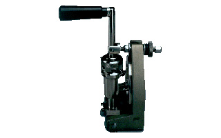
Tools
Flanging die for HCA 1-5/8" Size B
Manual Jacket Stripping Tool
Stripping tool for high speed grounding kit GKSPEED-114 series
Stripping tool for high speed grounding kit GKSPEED-158 series
Hand tool kit for the installation of connectors and grounding kits on CELLFLEX® Cables
Combination preparation tool (Universal Trimming Tool), CELLFLEX® Cable 1 5/8" for connector family OMNI FIT StandardC02
Flaring Tool LCFS/UCF 1 1/4" and LCF 1 5/8" for Universal Trimming Tools
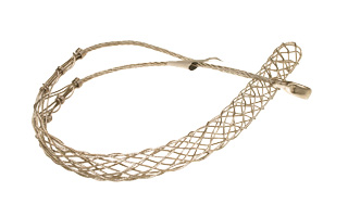
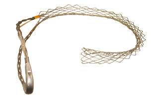
Hoisting Grip for Coaxial Cable and Elliptical Waveguide, Lace-Up
Hoisting Grip for Coaxial Cable and Elliptical Waveguide, Closed Lacing
Hoisting Grip for Coaxial Cable and Elliptical Waveguide, Closed Lacing
Hoisting Grip for Coaxial Cable and Elliptical Waveguide, Lace-Up
Automated trimming tool, LCF 158, OMNI FIT Premium, Trim Series D01
Automated trimming tool, LCF 114, LCFS114, OMNI FIT Premium, Trim Series D01
Combination preparation tool, crank version, for CELLFLEX® LCF 114, 158 and 214 cables
Insert for Combination preparation tool (Universal Trimming Tool), CELLFLEX® Cable 7/8" for connector family OMNI FIT Standard C02
Insert for Combination preparation tool (Universal Trimming Tool), CELLFLEX® Cable 1/2" for connector families OMNI FIT Premium D01 and RAPID FIT 070/072
Insert for Combination preparation tool (Universal Trimming Tool), CELLFLEX® Cable 1 1/4" for connector family OMNI FIT Premium D01
Combination preparation tool (Universal Trimming Tool), CELLFLEX® Cable 1 1/4" for connector family OMNI FIT Standard C02
Combination preparation tool (Universal Trimming Tool), CELLFLEX® Cable 1 1/4" for connector families OMNI FIT Standard B32 and RAPID FIT 062/072
Combination preparation tool (Universal Trimming Tool), CELLFLEX® Cable 1 1/4" for connector family OMNI FIT Premium D01
Combination preparation tool (Universal Trimming Tool), CELLFLEX® Cable 1 5/8" for connector family OMNI FIT Premium D01
Insert for Combination preparation tool (Universal Trimming Tool), CELLFLEX® Cable 1/2" for connector family OMNI FIT Standard C02
Insert for Combination preparation tool (Universal Trimming Tool), CELLFLEX® Cable 1 5/8" for connector family OMNI FIT Premium D01
Insert for Combination preparation tool (Universal Trimming Tool), CELLFLEX® Cable 1 5/8" for connector family OMNI FIT Standard C02
Insert for Combination preparation tool (Universal Trimming Tool), CELLFLEX® Cable 1 1/4" for connector families OMNI FIT Standard B32 and RAPID FIT 062/072
Insert for Combination preparation tool (Universal Trimming Tool), CELLFLEX® Cable 1/2" for connector families OMNI FIT Premium D01, OMNI FIT Standard family B32 and RAPID FIT 060/062 + 070/072
Combination preparation tool (Universal Trimming Tool), CELLFLEX® Cable 1/2" for connector families OMNI FIT and RAPID FIT
Insert for Combination preparation tool (Universal Trimming Tool), CELLFLEX® Cable 1 1/4" for connector family OMNI FIT Standard family C02
Combination preparation tool (Universal Trimming Tool), CELLFLEX® Cable 1/2" for connector family Omni Fit C02
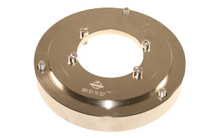
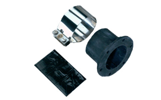
Wall Feedthrough Sealing
Feed through assemblies for 1 1/4" coaxial cable, 102mm (4"), 1-entry
Feed through assemblies for 1 5/8" coaxial cable, 102mm (4"), 1-entry
Wall feed through (without feed through plate)
Cold shrink tube, 1/2" to 5/8", 5/8" to 7/8"
Cold shrink tube, 1/2" to 1-1/4", 1/2" to 1-5/8", 5/8" to 1-1/4", 5/8" to 1-5/8", 7/8" to 1 1/4", 7/8" to 1 5/8"
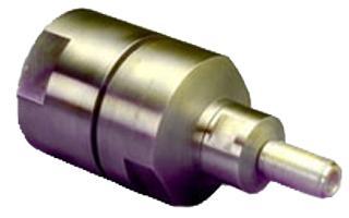
Connectors
N Female Connector for 1-5/8" Coaxial Cable, Straight O-ring sealing, Brass/Silver
4-1/2" IEC Connector for 5" Coaxial Cable, Gas stop, Sealing compound
N Male Connector for 1-5/8" Coaxial Cable, OMNI FIT standard, O-ring sealing
N Female Connector for 1-5/8" Coaxial Cable, OMNI FIT standard, O-ring sealing
7-16 DIN Male Connector for 1-5/8" Coaxial Cable, OMNI FIT™ standard, O-ring sealing
7-16 DIN Female Connector for 1-5/8" Coaxial Cable, OMNI FIT™ standard, O-ring sealing
N Male Connector for 1-5/8" Coaxial Cable, OMNI FIT™ Premium,
Straight, O-Ring and compression sealing
N Female Connector for 1-5/8" Coaxial Cable, OMNI FIT™ Premium,
Straight, O-Ring and compression sealing
7-16 DIN Male Connector for 1-15/8" Coaxial Cable, OMNI FIT™ Premium, Straight, O-Ring and compression sealing
7-16 DIN Female Connector for 1-5/8" Coaxial Cable, OMNI FIT™ Premium, Straight, O-Ring and compression sealing
N Male Connector for 1-1/4" Coaxial Cable, OMNI FIT™ Premium,
Straight, O-Ring and compression sealing
N Female Connector for 1-1/4" Coaxial Cable, OMNI FIT™ Premium,
Straight, O-Ring and compression sealing
7-16 DIN Male Connector for 1-1/4" Coaxial Cable, OMNI FIT™ Premium,
Straight, O-Ring and compression sealing
7-16 DIN Female Connector for 1-1/4" Coaxial Cable, OMNI FIT™ Premium, Straight, O-Ring and compression sealing
N Male Connector for 1-1/4" Coaxial Cable, OMNI FIT standard, O-ring sealing
N Female Connector for 1-1/4" Coaxial Cable, OMNI FIT standard, O-ring sealing
7-16 DIN Male Connector for 1-1/4" Coaxial Cable, OMNI FIT™ standard, O-ring sealing
7-16 DIN Female Connector for 1-1/4" Coaxial Cable, OMNI FIT™ standard, O-ring sealing
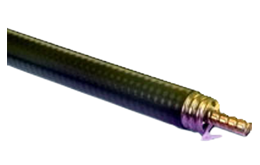
Coaxial Transmission Line
1-5/8" Air Dielectric Cable
1-5/8" Air Dielectric Cable, flame retardant/ halogen free jacket
1-5/8" Air Dielectric Cable
1-5/8" CELLFLEX® Premium Attenuation Low-Loss Foam-Dielectric Coaxial Cable
1-5/8" CELLFLEX® Premium Attenuation Low-Loss Foam-Dielectric Coaxial Cable
1-1/4" CELLFLEX® Premium Attenuation Low-Loss Foam-Dielectric Coaxial Cable
1-1/4" CELLFLEX® Premium Attenuation Low-Loss Foam-Dielectric Coaxial Cable
1-1/4" CELLFLEX® Premium Attenuation Low-Loss Foam-Dielectric Coaxial Cable
Grounding Kit
High speed grounding kit for CELLFLEX® LCF 158
High speed grounding kit for CELLFLEX® LCF 114
Grounding Kit, Pre-formed Copper Strap, 1.5m (60") for CELLFLEX® 1-5/8" Cable